


How I learned to stop worrying and love the BDL168
Well, perhaps that’s a bit strong, but I’m coming to terms with its design flaws and the poor state of the documentation surrounding it and the PM42. I now have the first set of PM42 circuit breakers and BDL168 occupancy detectors (with two sets of RX4 “transponding receivers”) installed, and have done a bit more reading over the weekend. I’ve discovered a few things and come to a few conclusions as a result of that work, and that’s making me feel that I have a handle on this now. But I had to work through a number of issues to get to this point.
First, wire gauge: while DCC bus wires need to be heavy gauge, typically 14 to 16 gauge, to avoid voltage drop problems (particularly an issue with high-amperage currents from DCC boosters), feeders can be much smaller. Even 22 gauge is safe for 5 Amps, if the wire is short (to avoid voltage drops) and mostly in open air (to allow it to radiate heat from all that current). I was already making use of this by using Kato’s 24 ga feeders (which are safe for 3 Amps; as a result, the trip current for the PM42 will be set to 3 Amp or less). I’d planned to use 16 ga for all wiring to those feeders (which can be several feet in length) to minimize voltage drops, and not being able to attach that to the card edge connectors was a large source of frustration for me.
Digitrax doesn’t say much about wire gauge (aside from a vague reference to 12ga wire being needed “for long wires” in the PM42 manual) for these systems, and it took some digging (and some experimentation) to turn up some facts and a recommendation from Digitrax. The card edge connectors for both the PM42 and BDL168 support 20 gauge wire, although you can use 18 gauge stranded wire with some effort, if you really need to. And hidden away in Digitrax’s documentation is the intent that you’d use short wires of 20ga (or similar) from the edge connector to a terminal strip, and heavier wire from the terminal strip if you need it. They don’t actually say this anywhere obvious though, and I’d missed it on my original pass through the documents that came with the equipment (because it’s not in them).
My intent all along had been to wire the PM42/BDL168 with terminal strips to allow for modular replacement without undoing too much work, so this lines up well with my plans. I just needed to adjust for the smaller gauge wire on this stretch of the wiring, and could continue using the 16ga wire I’d planned for the connection from the track feeder terminal strips to the BDL168 output terminal strip (these are the wires that run through the RX1 sensors; there’s a diagram on my Occupancy Detection page if you want more detail).
Soldering: on a related note, it’s much, much easier to solder 20ga wires to the edge connectors than 18ga. Much of my frustration with this connector was due to trying to use wire that really was too large. I did the PM42 using 18ga wire, but switched to 20ga for the BDL168, and it went much faster and more smoothly. It’s still a pain: the connectors are really close, and avoiding bridging two of them when using twisted-pair wires requires a great deal of care. Frequent application of some small nippers to remove stray strands of wire were required.
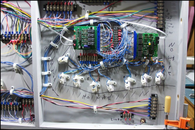
Real estate: as you can see from the photo above, things got a bit crowded, even with only 8 blocks wired to the BDL168 here. It’s clear I significantly underestimated the real-estate needed for this system. Hopefully it will still work (I did maintain the required 2” clearance around the actual RX1 sensors). The manual only talks about the space needed for the RX1 sensors, and doesn’t mention the need for terminal strips or the space for wires to/from them. And while I thought I’d left enough space for that, it’s clear I hadn’t. At a minimum, I think you need an area about 18” x 18” clear for a PM42, BDL168 and two sets of RX4 sensors, and 18” x 24” would probably be better (the BDL168 manual states that you need about 5.5” x 8” per RX4 set, not counting where the BDL168 is mounted).
I’m now thinking of doing something different on the later systems. In Digitrax’s application note on the PM42/BDL168 (PDF, hidden away in a Knowledge Base article on Transponding) there are a couple of photos showing a system like this mounted to a board that folds down from under the layout. I’d considered something like that in my original design (there’s a small except from one of those photos in the RX4 manual), and decided not to do it due to some clearance issues. I’m now re-thinking that, and will probably do something along those lines for the Urban Station and other detectors, to make installation and maintenance easier, and to provide for more space for mounting terminal strips.
Power: The BDL168 is varyingly described as needing a minimum of “12 volts AC or DC” or “12 volts AC or 13.8 volts DC”. It’s also clear, and I should have realized this, that you can’t power the PM42 from the same supply powering the Booster it’s protecting. The reason appears to be that in a short voltage will drop to close to zero before the circuit breaker severs the connection (that and/or the high current is what causes it to react), and this would affect the operation of the PM42 (you’d think they could do something with a capacitor to ride through this, but apparently they didn’t). So, I can’t use one quarter of my PS2012 for the “accessory bus” as planned. I’m still debating whether to separately power each PM42 (the safest solution) and leave the bus for DS64 turnout controls and other things that can be powered off the PS2012, or to find a large power supply (2 amps+), possibly at 14 volts, to use for the bus. The ambiguity in power requirements is annoying. From the context, I think that 12 volts is safe, and they only said 13.8 because the new PS14 (which replaced the older 12-volt PS12) puts out 13.8 volts, and they’re now recommending use of it. I did try posting a question to Digitrax using their KB, but got no answer after a week; maybe I’ll send them an email.
Flexibility: Transponding is really badly documented. There is some information in the manual that comes with the RX4 (PDF), there’s more in a supplement note that goes with the BDL168 (PDF), and there’s the application note mentioned above and various KB articles that touch on the topic. It would appear from the KB article, that it actually is possible to use the same RX1 sensor with two or more blocks by running more than one wire through it. You can also (and I knew this) monitor all blocks associated with a single power input to the BDL168 by putting the RX1 on the line into the BDL168 (between the PM42 and BDL168) rather than on the output (BDL168 to track feeder).
While I’m content with my current design, it’s nice to know I could use all 16 detectors with a more flexible set of transponding zones than the 4:1 input-based approach I thought was the only alternative to monitoring only half the blocks.
So the current status is that the left half of the Riverside Station is now fully wired. The right half has nearly as many wires, but should go faster now that I’ve had some experience. While doing this work, I also added the two wires for the Lighting power bus (my 12v, 1.5A power supply for LED lights). I’m going to take advantage of that with the right table to wire lights into the Subway station before I reassemble things. I’m going to be using LED Strip lighting; for details on that, see my LED Strip Lighting page, which will be updated to reflect that work as it gets done.
Other website changes:
- Photos added to the Construction and Electronics albums, and diagrams added to the Diagrams album.
- Updated the “Phase 2k” Construction page with more words about recent work.
- Updated the DCC Wiring and Power Wiring Standards pages to reflect changes in my plans. Mostly this is just minor changes like wire gauge or color-codes used for different things, and updating really old text to reflect changes I made months ago.
- Updated my Reservations page (to note a delay to the Tomix Toei bus set).
== Comments from old system:
Tuesday, March 8, 2011 - 02:41 AM
Don
Wow, that's really insane. The photo says it all. There has to be a simpler way!
Thursday, March 10, 2011 - 02:17 AM
quinntopia
Interesting, I feel a lot of the pain your sharing! It has always struck me how we keep hearing/reading about the need for larger gauge bus wires, but nearly every power connection (other than some sort of screw in terminal) seems like its 20 gauge or higher. Digitrax's implied comment about how they 'think' people would solve this is interesting.
Friday, March 11, 2011 - 03:10 AM
KenS
Yes, we tend to focus on bus wires with DCC, which need to be moderately large to avoid loss over longer distances when carrying high current. But the point is stressed so much, that most people don't realize that for a typical small layout with 3 Amps or so of maximum current, even 16 gauge would be more than sufficient. And for short lengths, voltage drop isn't a significant issue, and relatively small wires can do just fine. Proper wiring for things like occupancy detectors and circuit breakers gets next to no discussion.
Part of that is probably just due to simplifying a complex subject. If you say "use 14 gauge wire", then that's a simple statment, and people won't get in trouble if it's a large or small layout, and if it's using 3 amps or 8. But it creates the mindset that wire always needs to be heavy for DCC, and that can be misleading (I certainly got all twisted up, and I should know better).
